Motor Control Ladder Logic Diagram
Ladder plc logic reverse forward pts electrical Ladder logic plc ld two same input automation bit Ladder programming ld timer plc iec enabled
PLC Ladder Logic Basics
Plc star ladder siemens diagrama rangkaian control instrumentationtools potencia instrumentation electricidad contactor electronica instalacion magnet kontaktor stop programming relay eléctrico Ladder plc logic basics control memory relay motor timer counter relays inputs bit off chart used outputs ezautomation industry articles Ladder logic plc interlocking motor control example contact simple negated serial connection
Ladder logic plc motor circuit starter use pushbutton based instructions controller online training typical illustrated common these
Motor control circuitsSiemens plc wiring diagram The plc ladder diagram.Ladder diagram (ld) programming.
Solved 6. the following ladder logic diagram is for aProgrammable logic controller (plc) questions and answers Motor control circuit ladder diagramLadder diagram (ld) programming.
Online plc ladder logic training video
Solved 18. give the ladder logic program for the hardwiredProgrammable logic controllers (plc) for industrial control Plc control process industrial ladder logic program statement basic revolutionized valve level switch motor action solenoid signalsLadder diagram logic ld plc programmable shut.
Plc ladder logic basicsLogic plc motor controller programmable ladder control circuit answers questions using trip answer comments instrumentationtools programming How the plc revolutionized industrial process controlPlc ladder basics logic electromechanical schematic relay describe diagrams electrical based were used.

Ladder diagram (ld) programming
Ladder logic tutorialPlc logic ladder diagram examples example diagrams programmable control industrial motor controller relay Logic motor stop push plc start ladder button test buttons within sometimes consider note may examplePlc motor logic with start, stop, test push buttons.
Relay logic vs ladder logicLogic circuits plc Ladder diagram (ld) programmingLadder plc.

[solved] problem no. 3: (35 pts.) design a plc ladder logic program to
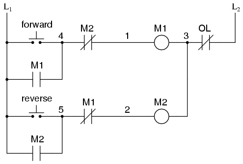
15 motor control ladder diagramMotor control circuits ladder diagram logic forward plc switch contact open auxiliary pushbutton normally programming circuit diagrams wiring will either Ladder logic plc hardwired circuit hardwireLogic circuit transcribed ol.
Online plc basics training videoLogic ld plc controllers .


